Products

Heating cables, accessories, sensing, and engineered packages designed for stable operation in industrial environments.

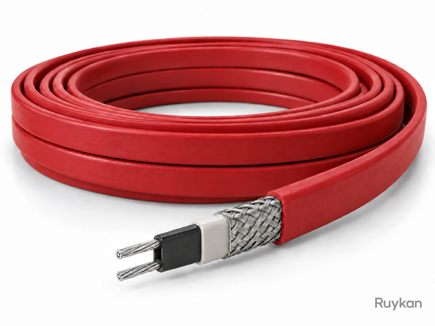
Low-Temperature Self-Regulating Heat Tracing Cable
01

Low-Temperature Self-Regulating Heat Tracing Cable

The low-temperature self-regulating heat tracing cable uses two parallel bus wires and a PTC semiconductor polymer heating core tape. The core tape automatically adjusts output according to local pipe temperature changes: power increases when the temperature drops and decreases when the temperature rises. It is suitable for freeze protection, anti-freezing, and maintaining process temperatures up to 65°C for pipelines, valves, tanks, and equipment in water supply and drainage, fire protection, petrochemical, and other industries.

  • PTC core tape adjusts heating output segment by segment, adapting to different heat dissipation at various pipe positions
  • Parallel busbar structure, can be cut to installation size within the specified maximum loop length
  • self-regulating feature reduces the risk of continuous overheating at overlapping installation positions
Rated voltage
220V / 380V
Rated output power (10°C)
10 / 15 / 20 / 25 / 30 / 35 W/m
Maximum maintained temperature
65°C
PVC-Insulated Heating Wire
02

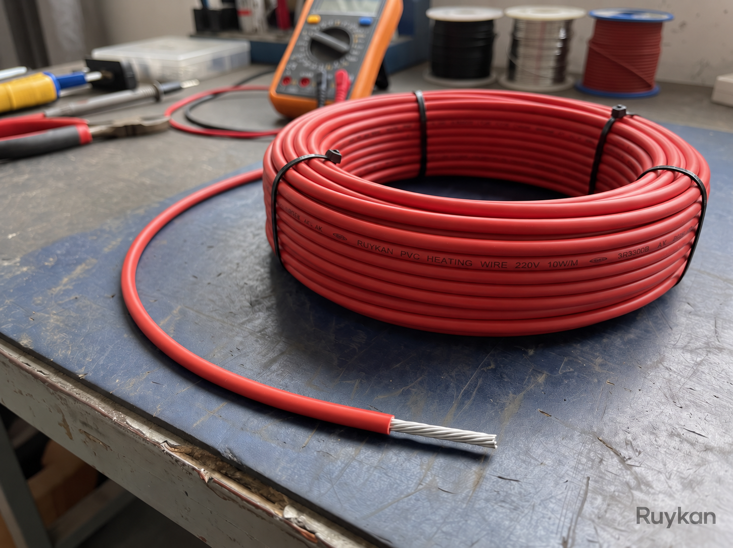
PVC-Insulated Heating Wire

PVC insulated electric heating wires are made by winding nichrome or copper-nickel resistance wire on a fiberglass core, then extruding it with heat-resistant PVC insulation. The wires are soft and easy to shape, suitable for defogging door frames, low-temperature compensation, and low-power defrosting in refrigerators, freezers, vending machines, and ice makers. They can also be made into aluminum foil laminated heating elements. The heating length, resistance per meter, cold ends, terminals, and total power are matched according to the equipment voltage and allowable surface temperature.

  • Nichrome or copper-nickel heating wire is wound on a fiberglass core; the wire is soft and easy to shape
  • Available in heat resistance grades of 75°C, 95°C, and 105°C, which can be selected according to the allowable temperature of the equipment
  • The standard low-load structure has a maximum of 8 W/m, and the 105°C grade structure has a maximum of 12 W/m
Heating element
Nickel-chromium or copper-nickel resistance wire
Core wire
Fiberglass core wire
Insulating material
Heat-resistant PVC
Silicone Rubber-Insulated Heating Wire
03

Silicone Rubber-Insulated Heating Wire

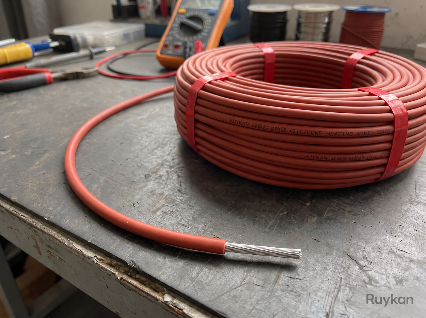
Silicone rubber insulated electric heating wires use nickel-chromium or copper-nickel resistance wires as the heating element, wound on a fiberglass core and extruded with a single or double layer of silicone rubber insulation. The wire is flexible and can be arranged along refrigerator and freezer evaporators, door frames, drip trays, drain pipes, and surfaces of small equipment, for defrosting, anti-condensation, anti-freezing, and heat preservation; the heating length, cold end, resistance per meter, total power, and leads with terminals are matched according to the equipment voltage and installation dimensions.

  • Nickel-chromium or copper-nickel heating wire wound on a fiberglass core, combining flexibility and resistance stability
  • Single or double layer silicone rubber insulation adapts to low temperature, humid, and repeated hot and cold cycling environments
  • Maximum 40 W/m line power suitable for defrosting, anti-condensation, and drain frost protection in refrigeration equipment
Heating element
Nickel-chromium or copper-nickel resistance wire
Core wire
Glass fiber core wire
Insulation structure
Single-layer or double-layer silicone rubber insulation
Medium-Temperature Self-Regulating Heat Tracing Cable
04

Medium-Temperature Self-Regulating Heat Tracing Cable

The medium-temperature self-regulating heat tracing cable uses parallel bus wires and PTC semiconductor polymer heating core tape, which can automatically adjust the output according to local temperature changes of the pipeline. It is suitable for antifreeze, anti-condensation, and 0–105°C process temperature maintenance of industrial pipelines, valves, storage tanks, and equipment in petroleum, chemical, steel, and power industries.

  • The PTC core tape adjusts the heating output in segments to compensate for heat loss variations at different positions of the pipeline.
  • The parallel loop structure allows cutting according to installation size within the specified maximum loop length.
  • 35 / 45 / 50 / 60 W/m power levels cover medium-temperature antifreeze and process temperature maintenance requirements.
Rated Voltage
220V / 380V
Rated Output Power (10°C)
35 / 45 / 50 / 60 W/m
Maximum Maintaining Temperature
105°C
Aluminum-Tube Defrost Heating Wire
05

Aluminum-Tube Defrost Heating Wire

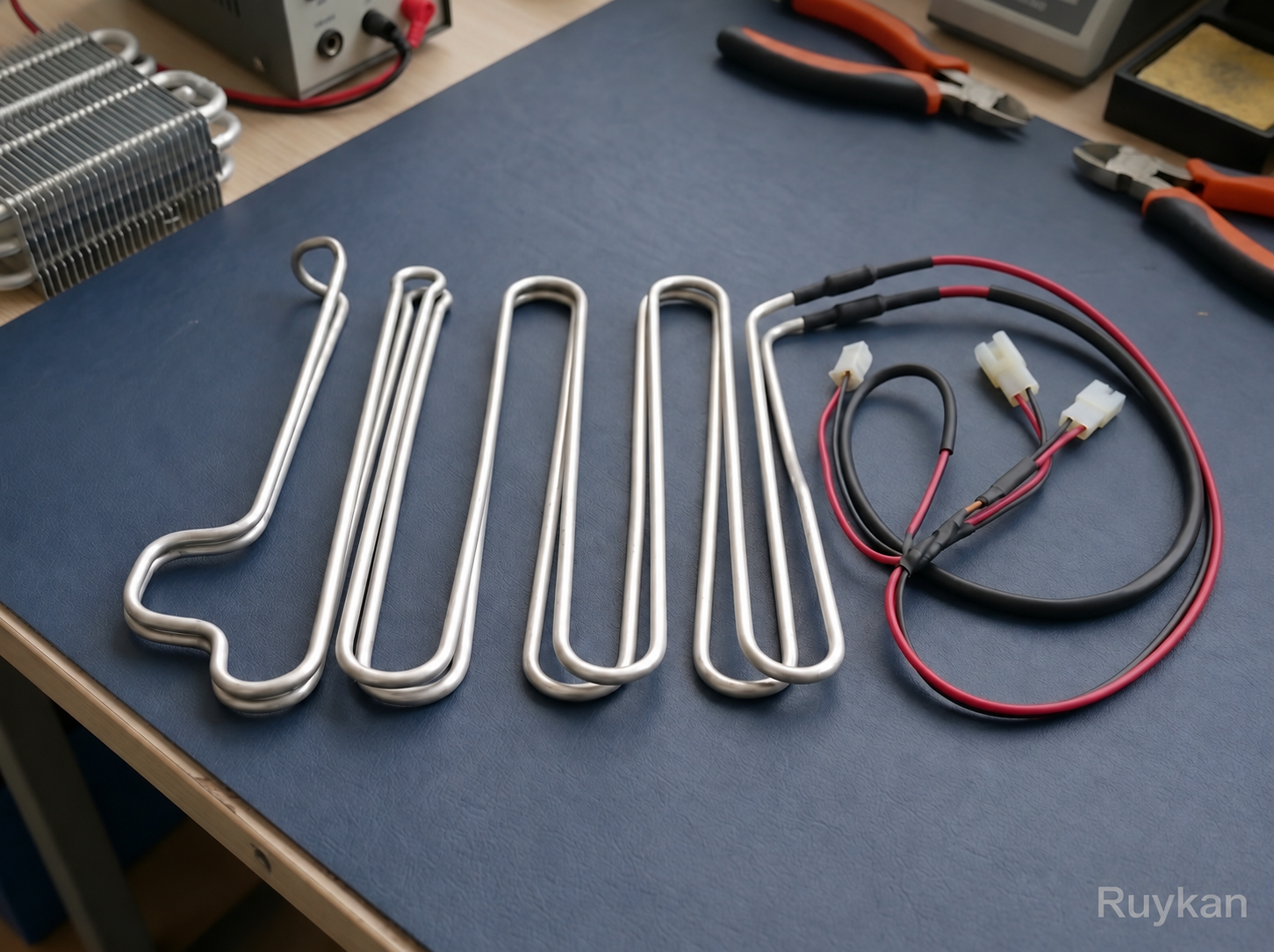
The aluminum tube defrost heating wire places single-layer or double-layer silicone rubber insulated heating wire into a formable aluminum tube. The tube transfers heat to the evaporator, water pan, or drainage area, and is used for defrosting and anti-freezing in refrigerators, freezers, display cabinets, and commercial refrigeration equipment. The tube shape, heating section, cold end, lead, and terminal can be matched according to the equipment installation space, and the system should be controlled by a thermostat, defrost controller, or thermal protector.

  • Formable aluminum tube combines heat conduction, mechanical protection, and arrangement in limited space
  • Single-layer or double-layer silicone rubber insulated heating wire is suitable for humid, frosty, and low-temperature environments
  • Maximum linear power for refrigeration equipment application is 35 W/m, facilitating the control of local heat load
Rated voltage
≤240 V AC
Refrigeration equipment line power
≤35 W/m
Aluminum tube outer diameter range
2–10 mm (tolerance ±0.2 mm)
High-Temperature Self-Regulating Heat Tracing Cable
06

High-Temperature Self-Regulating Heat Tracing Cable

The high-temperature self-regulating heat tracing tape uses a semiconductor self-regulating heating core tape and parallel circuits that can be cut on-site. It automatically adjusts output along the heating loop according to ambient temperature and thermal loss of the insulation layer. It is suitable for frost protection and maintaining a process temperature up to 150°C for high-temperature process pipelines, valves, instrument lines, storage tanks, and equipment, and can withstand intermittent high temperatures caused by steam purging.

  • The semiconductor heating core tape adjusts output section by section along the loop to compensate for local heat loss changes.
  • The parallel loop structure allows cutting to on-site dimensions within the specified maximum loop length.
  • 10 / 20 / 30 / 39 / 49 / 66 W/m power ratings cover different high-temperature maintenance loads.
Rated Voltage
220–240V AC
Rated Output Power (10°C)
10 / 20 / 30 / 39 / 49 / 66 W/m
Maximum Sustained Temperature
150°C
Parallel Constant-Wattage Heat Tracing Cable
07

Parallel Constant-Wattage Heat Tracing Cable

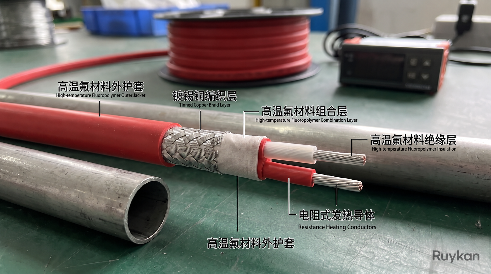
The parallel constant-wattage heat tracing cable uses two parallel insulated copper busbars and periodically connected resistance heating wires to form continuous parallel heating units. After electrification, it maintains a stable output per unit length and is suitable for frost protection, insulation, and process temperature maintenance for industrial pipelines, valves, instruments, storage tanks, and equipment; temperature control and circuit protection must be used during operation.

  • Continuous parallel heating units provide stable output power per unit length
  • Can be cut to integer multiples of the heating section length, with on-site connection to power supply and end accessories
  • 20 / 25 / 30 / 40 / 60 W/m power levels cover frost protection and process temperature maintenance requirements
Rated Voltage
220V / 380V AC
Rated Output Power
20 / 25 / 30 / 40 / 60 W/m
Power and Maximum Sustained Temperature
20 W/m: 60°C; 25 W/m: 80°C; 30 W/m: 100°C; 40 W/m: 130°C; 60 W/m: 150°C
Series Constant-Wattage Heat Tracing Cable
08

Series Constant-Wattage Heat Tracing Cable

The series constant-power heat tracing cable uses a metal conductor with a specified resistance as the heating element. When energized, it continuously generates heat along the entire finished circuit through Joule heating. It is suitable for long-distance pipelines, valves, pump housings, and instrument lines that exceed the length limitations of self-regulating and parallel constant-power electric trace heating circuits. Freeze protection, insulation, and process temperature maintenance for the longest 3.6 km circuit can be completed from a single power supply point.

  • The series resistance circuit provides a stable heat output per unit length along the entire finished length.
  • A single circuit can reach up to 3.6 km, suitable for reducing the number of power supply points for long pipelines.
  • Available in single-core, double-core, and triple-core structures to accommodate different voltages and electrical connection methods.
Rated Voltage
220V / 380V / 660V AC
Structural Form
Single-core, double-core, three-core series constant power circuit
Longest Single Circuit
3.6 km
Gutter Snow-Melting Heating Cable
09

Gutter Snow-Melting Heating Cable

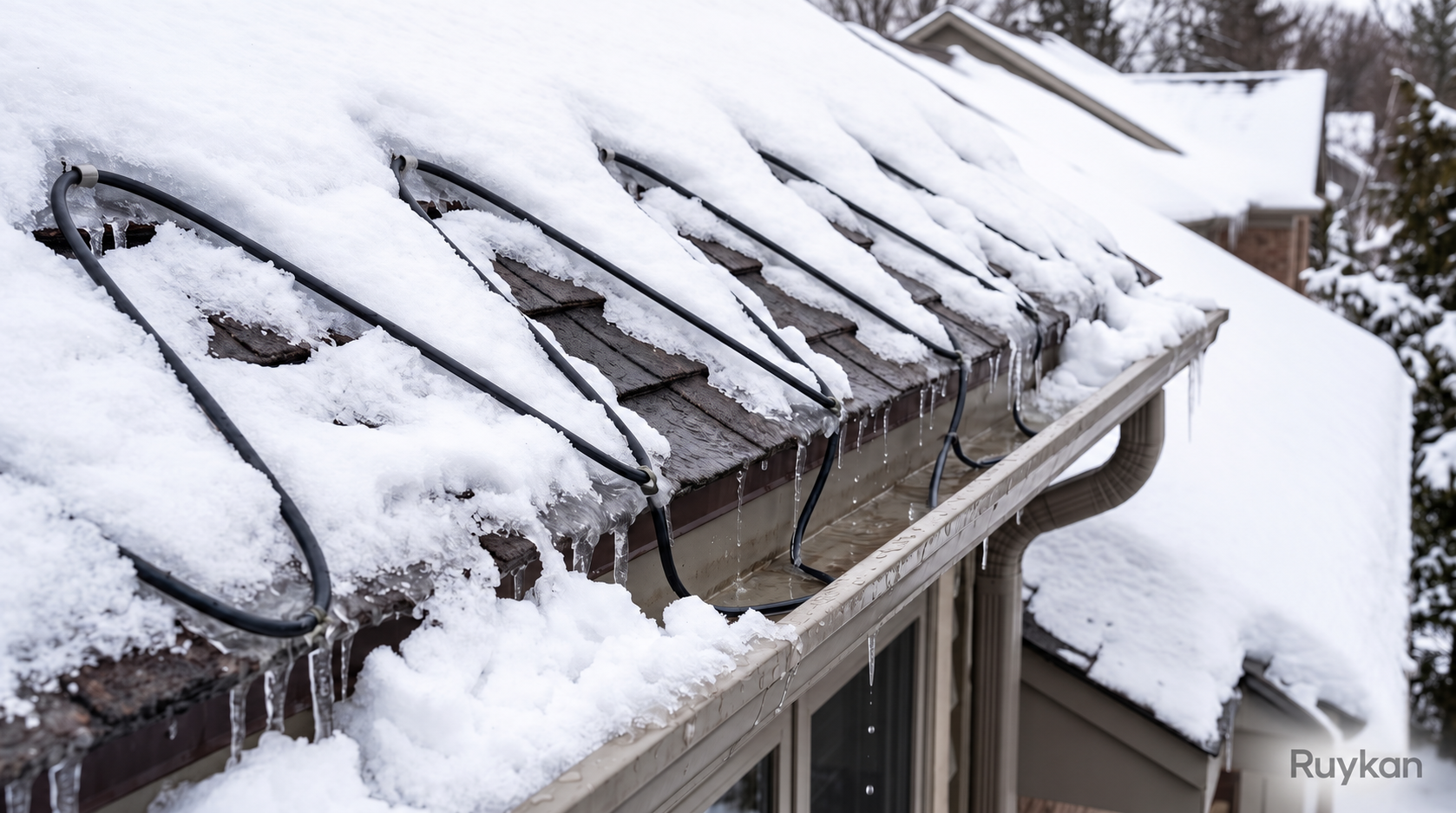
The gutter snow-melting heating cable uses a parallel self-regulating heating core cable, which can be installed along eaves, roof drainage paths, gutters, and downspouts. When covered with ice and snow, the cable automatically increases output to form a continuous drainage channel, and reduces output once the surface is dry; used together with temperature, humidity, or ice-and-snow controllers, it can automatically start and stop according to actual weather conditions.

  • Specifically designed for snow and ice melting on eaves, gutters, downspouts, and roof drainage paths.
  • The self-regulating heating core cable adjusts heating output section by section according to ice and snow coverage and ambient temperature.
  • Parallel circuits can be cut according to the on-site layout path within the allowable circuit length.
Rated Voltage
110–120V or 208–277V AC
Rated Output in Snow and Ice (0°C)
39 W/m
Rated Output in Dry Air (0°C)
20 W/m
Silicone Rubber Heating Tape
10

Silicone Rubber Heating Tape

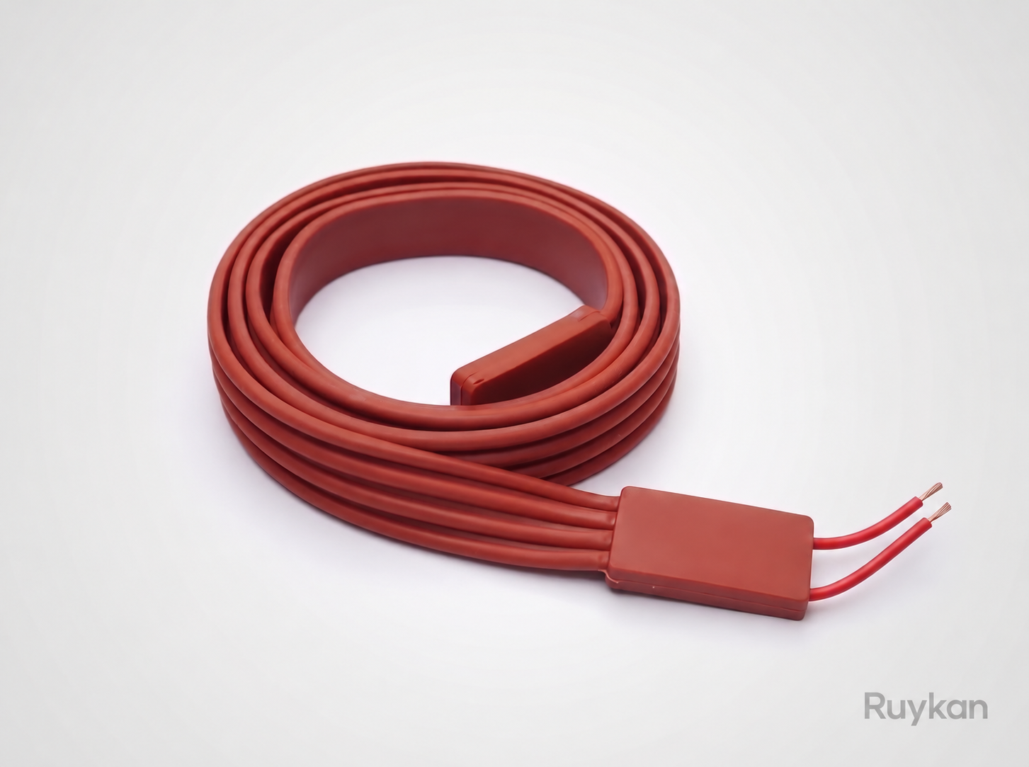
The silicone rubber electric heating tape uses a glass fiber woven framework and a resistive heating element, with an overall external flexible silicone rubber coating. The tape body can be attached to or wrapped around pipes, valves, containers, laboratory equipment, and irregular surfaces for direct heating, frost protection, and insulation; when in use, it requires a matching temperature sensor and controller to limit the temperature of both the heated object and the tape.

  • Flexible silicone rubber tape can conform to flat, curved, and tubular equipment surfaces
  • Glass fiber woven framework reinforces the tape body, and the silicone rubber outer layer resists moisture and common chemicals
  • 13 / 25 / 51 mm tape width and various standard lengths can be selected according to the installation area
Rated Voltage
120V or 240V AC
Standard Bandwidth
13 / 25 / 51 mm
Standard Length
0.6–6.1 m (selected according to bandwidth and voltage)
Fiberglass Heating Tape
11

Fiberglass Heating Tape

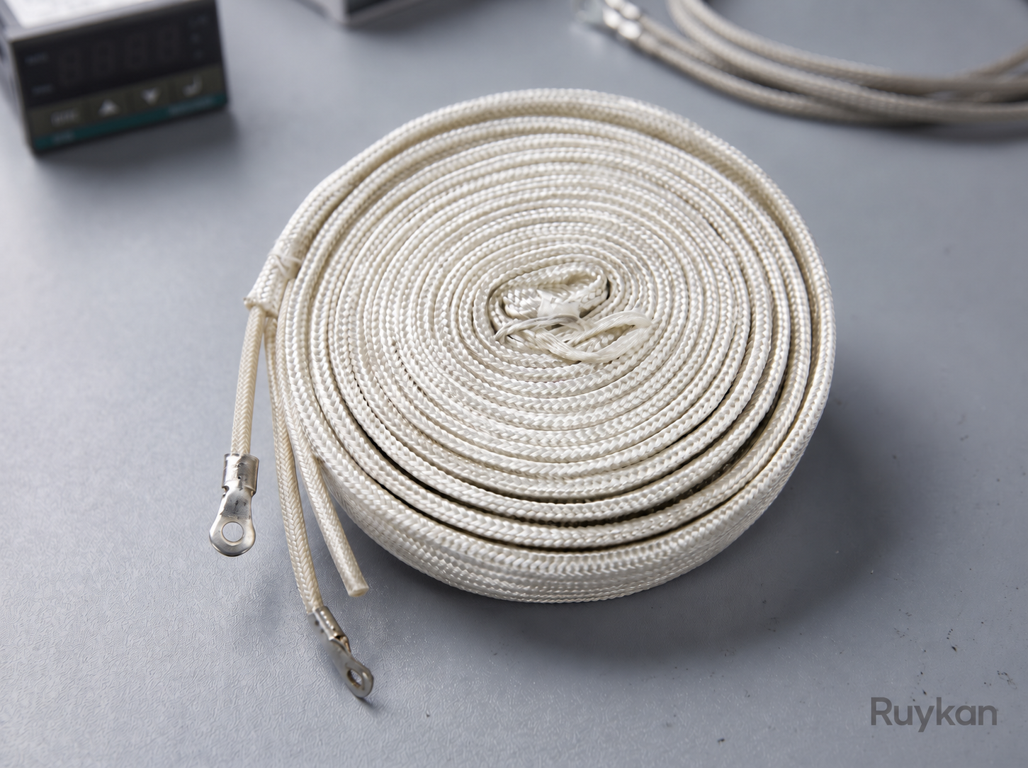
The fiberglass electric heating tape uses a resistance heating element wound around a fiberglass core, covered externally with a braided fiberglass sheath and a grounding braid layer. It can be wound along metal pipes, glassware, columns, valves, and transmission pipelines for high-temperature surface heating in dry environments; when in use, it must be paired with a power regulator or temperature controller.

  • The double-layer fiberglass insulation structure is suitable for heating element temperatures up to 450°C
  • The flexible tape of approximately 25 mm can conform to pipes, valves, columns, and glassware
  • 164 W/m line load and maximum 0.62 W/cm ² surface power density are suitable for high-power heating
Rated Voltage
115V or 230V AC
Standard Width
Approximately 25 mm
Standard Length
0.61 / 0.91 / 1.22 / 1.83 / 2.44 / 3.66 / 4.88 / 7.32 / 9.76 m
U-Shaped Liquid Tubular Heater
12

U-Shaped Liquid Tubular Heater

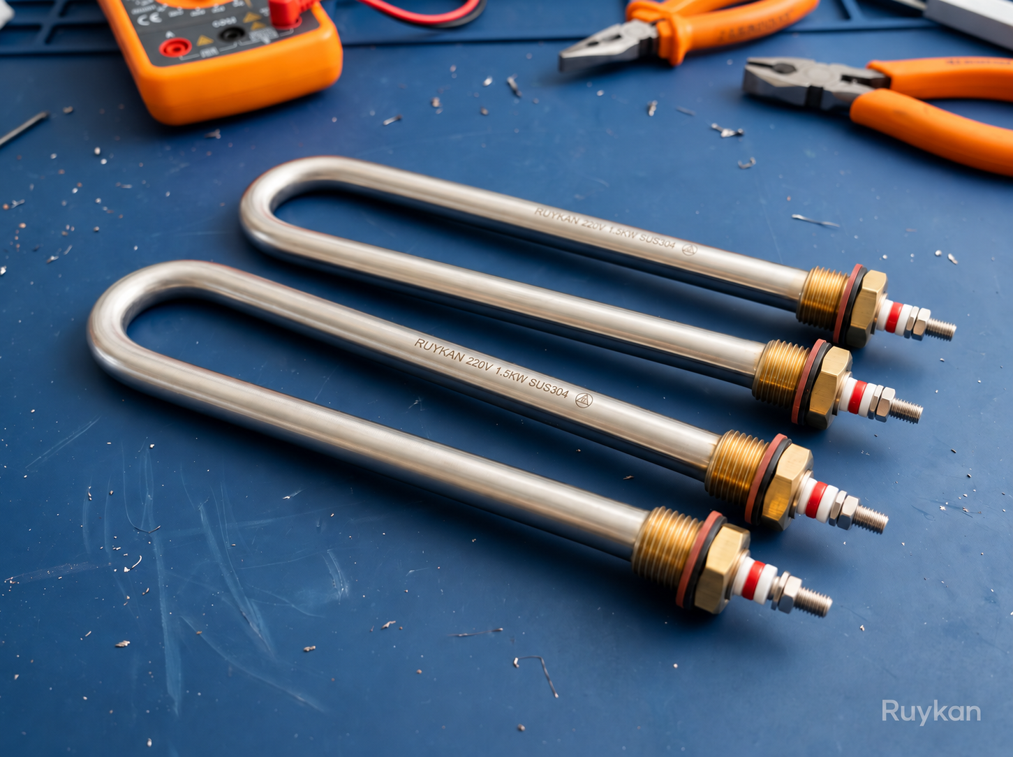
The U-shaped tubular heater for liquids encloses a nickel-chromium resistance heating wire centered within a metal tube, with insulation and thermal conductivity achieved by compacting high-purity magnesium oxide. After bending the tube into a U shape, it can be directly immersed in water, cleaning solutions, heat transfer oil, or fuel oil, with both terminals located outside the container. The surface load, sheath material, and total power must be designed according to the thermal conductivity, viscosity, corrosiveness, target temperature, and liquid flow conditions of the medium. During operation, the entire heating section must remain fully submerged and be equipped with a temperature controller, independent over-temperature protection, and low-liquid-level power-off interlock.

  • The U-shaped double-ended structure facilitates installation from the side wall or top of the tank or container, with external wiring completed outside.
  • Copper, 304 / 316L / 321 stainless steel, Incoloy 800 / 825 sheath can be selected according to water quality, oil type, and corrosion conditions.
  • Water heating uses 6–10 W/cm², light fuel oil 2–4 W/cm², heavy oil or high-viscosity medium 1–2 W/cm².
Basic Structure
Nickel-chromium resistance wire + compacted high-purity magnesium oxide + metal tube sheath
Structure Form
U-shaped double-ended immersion heating tube
Common Voltage
220 V / 380 V AC; special design up to 480 V
U-Shaped Air Tubular Heater
13

U-Shaped Air Tubular Heater

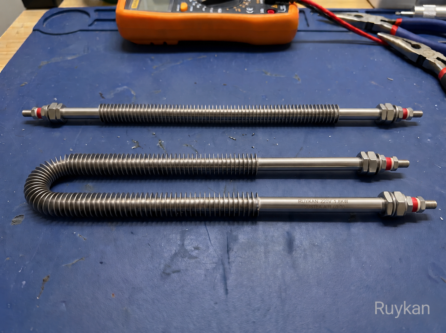
The U-shaped double-ended air heating element consists of a nickel-chromium resistance wire, compacted high-purity magnesium oxide, and a metal sheath, with both terminals located on the same mounting side. The element can be arranged in ovens, air ducts, drying equipment, and circulating hot air systems to heat air via natural convection or forced airflow. The power density must be determined according to the inlet air velocity, outlet temperature, allowable sheath temperature, and airflow uniformity; forced-air equipment should interlock the fan status with the heating power and provide operational temperature control and independent over-temperature protection.

  • The U-shaped double-ended design concentrates both terminals on the same mounting side, facilitating panel mounting, wiring, and maintenance.
  • Sheaths made of steel, 304/316L stainless steel, and Incoloy 800 are suitable for dry air, moist airflow, and high-temperature oxidizing environments.
  • The duct design is based on a minimum airflow of 61 m/min, a maximum surface load of 6.2 W/cm², and a maximum sheath temperature of 760°C.
Basic Structure
Nickel-chromium resistance wire + compacted high-purity magnesium oxide + metal tube sheath
Structural Form
U-shaped double-ended air heating tube, two terminals located on the same installation side
Common Voltage
220 V / 380 V AC; the air duct system can be designed up to 480 V