- Basic Structure
- Nickel-chromium resistance wire + compacted high-purity magnesium oxide + metal tube sheath
- Structural Form
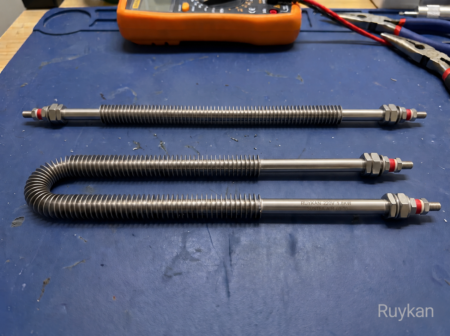
- U-shaped double-ended air heating tube, two terminals located on the same installation side
- Common Voltage
- 220 V / 380 V AC; the air duct system can be designed up to 480 V
- Power Supply Method
- Single-phase or three-phase, three-phase circuits are configured balanced according to the number of components and total power
- Common Pipe Diameters
- 6.25 / 6.6 / 8 / 9.5 / 10.9 / 12.7 mm
- Sheath Material
- Carbon steel, AISI 304 / 316L stainless steel, Incoloy 800
- Sheath Temperature Limit
- Carbon Steel 399°C; Stainless Steel 649°C; Incoloy 871°C
- Duct Design Limit
- Minimum Air Velocity 61 m/min, Maximum Surface Load 6.2 W/cm², Maximum Sheath Temperature 760°C
- Still Air Load
- Incoloy Sheath: 371°C at 4.65 W/cm²; 538°C at 3.10; 649°C at 1.55; 816°C at 0.31
- 2.74 m/s air flow load
- Incoloy sheath: 260°C at 6.20 W/cm ²; 427°C at 4.96; 538°C at 3.88; 649°C at 2.33; 816°C at 0.31
- Power calculation
- P = air volume (m³/h) × air density (kg/m³) × specific heat at constant pressure (J/kg·K) × temperature rise (K) ÷ 3600
- Dimension configuration
- Total length, heating length, cold end, U-shape spacing, bending radius, terminal length, and mounting parts are produced according to the drawing
- Installation Direction
- Airflow passes uniformly laterally through the heating section; terminals are placed outside the insulation layer, avoiding convection hot air and radiant heat
- Horizontal Support
- When installed horizontally at high temperature, provide support every 305–457 mm to prevent the component from sagging due to heat
- Thermal Expansion Allowance
- Reserve about 3.2 mm for thermal expansion in the length direction every 305 mm, do not rigidly lock the heating section
- Terminals and Sealing
- M4 / M6 studs, tabs, round pins, or welded leads; keep the wiring area clean, dry, and secure
- Temperature Control
- Install a working temperature sensor at the outlet; place an independent over-temperature limiter near the heating tube for faster response
- Fan Interlock
- The airflow switch or air pressure switch confirms airflow before allowing heating; cut off the heating power immediately when the fan stops
- Electrical Protection
- The metal sheath and frame are reliably grounded, and overcurrent and short-circuit protection suitable for the rated current is provided.
- Typical Applications
- Ovens, air ducts, circulating hot air furnaces, drying and curing equipment, dehumidifiers, and air reheating
- Selection Parameters
- Provide inlet/outlet temperature, minimum/maximum airflow and air velocity, air composition, working pressure, voltage, number of phases, power, installation diagram, and continuous/intermittent operation conditions